Power Check FAQ#
What is the “Power Check” method?
Power Check is a method used to verify the power performance of a solar thermal collector field. It involves a procedure to calculate the expected power output of the field based on parameters from ISO 9806, a safety factor, and measured operating conditions. The estimated power output is then compared to the actual measured power output to assess the collector field’s performance. In doing so, Power Check accounts for all major factors that influence the power performance of a collector field: the collectors used (ISO 9806 parameters), measured operating temperatures and weather data. Hence, Power Check performance results can be compared among plants in different geographical locations, using different collector technologies, running on different temperature levels and exposed to different climates.
The following figure, taken from Guide to ISO 24194:2022 Power Check, provides a step-by-step overview of the ISO 24194 Power Check procedure.
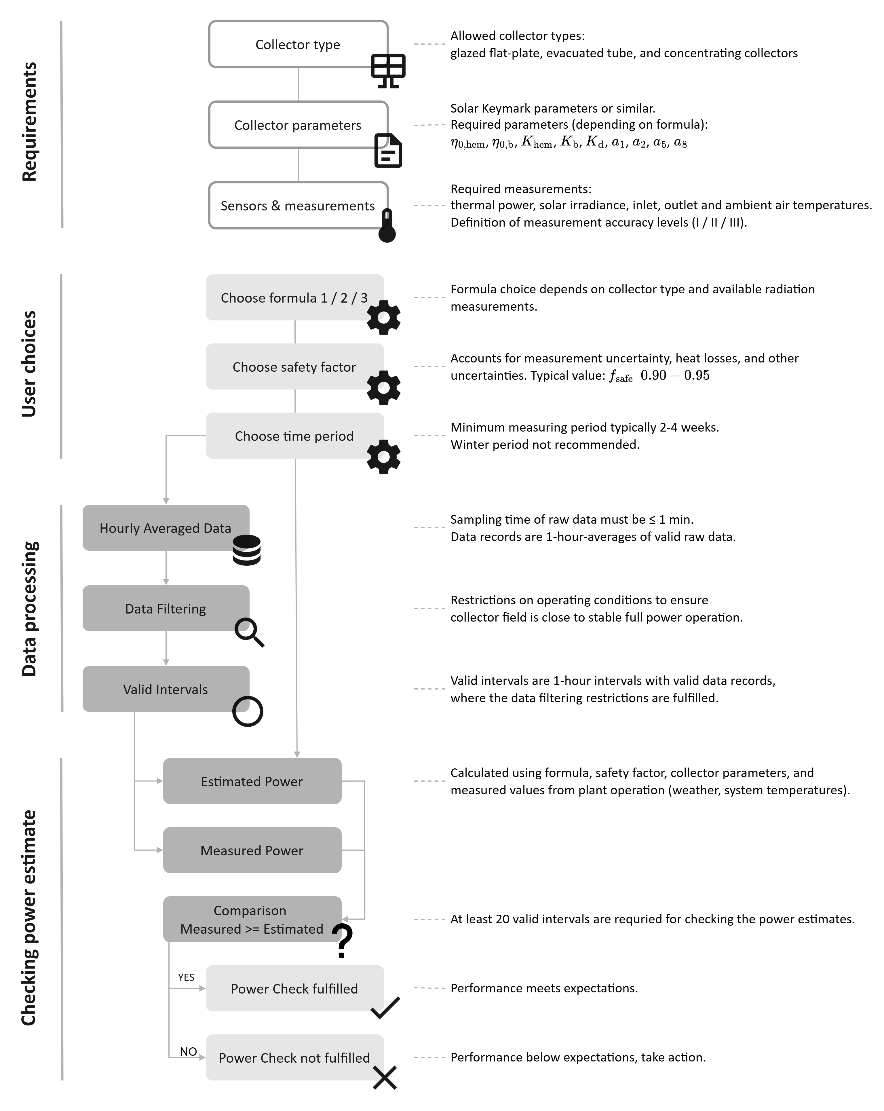
Step-by-step overview of the Power Check procedure according to ISO 24194.#
What are the main steps involved to perform Power Check?
The figure below summarizes the five main steps to a successful Power Check. See the FAQ questions below for more details.
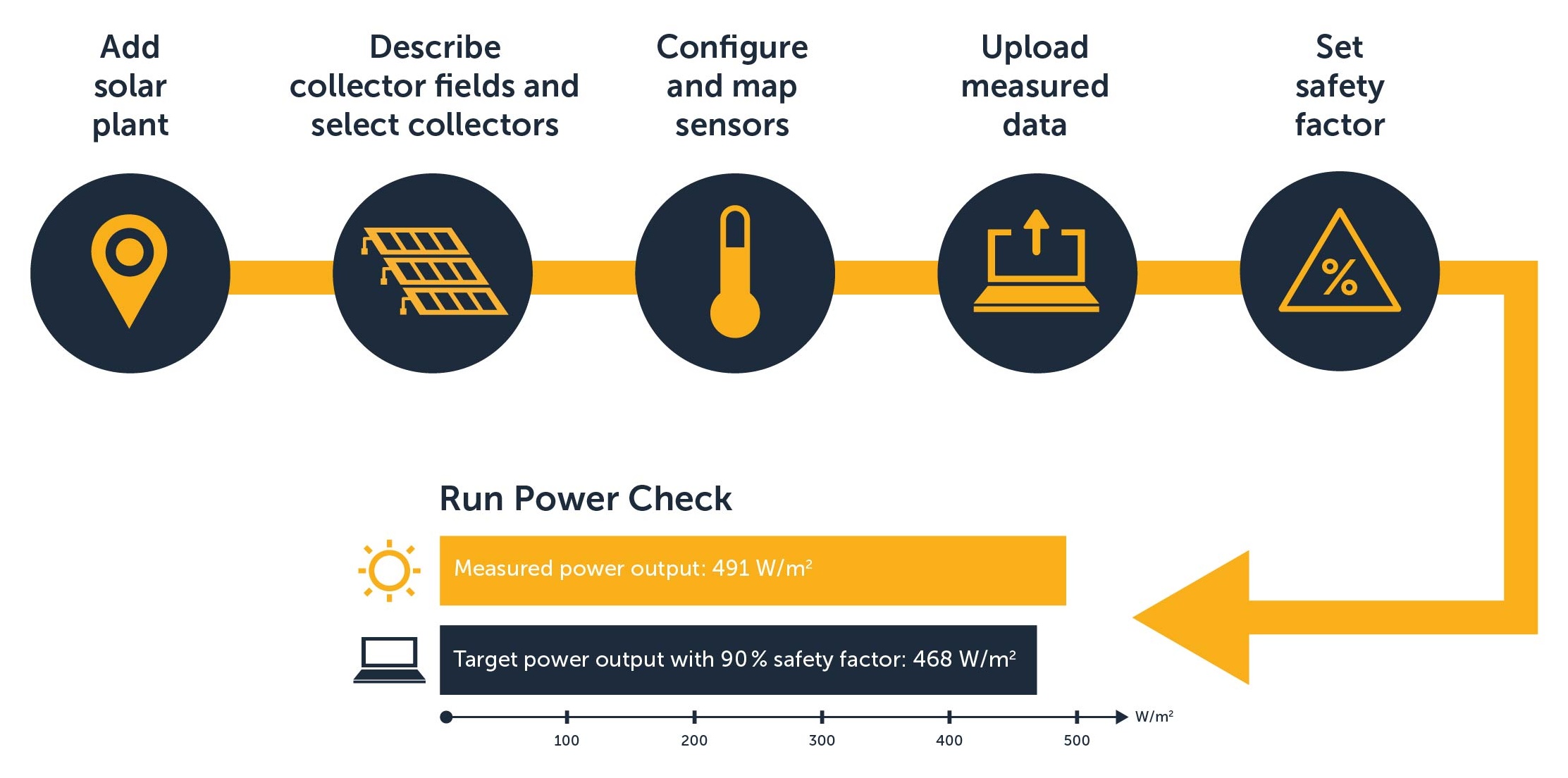
Overview of the main steps to run Power Check.#
How does Power Check work?
As explained in sunpeek-use-cases, Power Check covers two main uses: performance assessment and performance monitoring. Both use cases are based on ISO 24194, which describes how Power Check should be performed. In principle, the method includes the following steps:
Measurements and Data Acquisition: As a prerequisite, the ISO method requires some sensor measurements. On one hand, it needs a heat meter (or alternatively flow meter and temperature of flow and return) to calculate the measured power. And on the other hand, it requires irradiation, ambient temperature, and the collector temperature to compute the estimated power based on the Solar Keymark equation (ISO 9806).
Data Processing, Averaging: The measurement values are then averaged in 1h intervals.
Data Processing, Filtering: Next, the data is filtered so it only contains valid 1h intervals. These filters include a minimum irradiation (e.g., > 600 W/m²), stable operating conditions based on the collector temperature change (e.g. <= 5K), low wind velocity (< 10m/s), high enough ambient temperature (>5°C), and no collector-shading. These restrictions ensure a stable comparison between measurement and estimations.
Performance Comparison: Finally, estimated power is calculated using the Solar Keymark equation (ISO 9806). The estimated power is then compared with the measured power within “valid” intervals. To account for uncertainties, a safety factor (0-100%) is applied.
Analysis and Reporting: A PDF report is generated, summarizing the findings in a series of plots and tables.
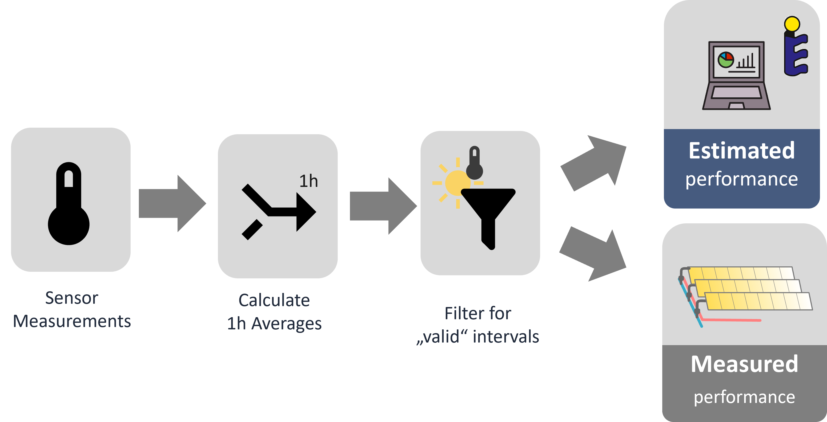
The following figure provides a high-level overview of the data processing steps performed by SunPeek. For more detailed information, see power-check-more-info.
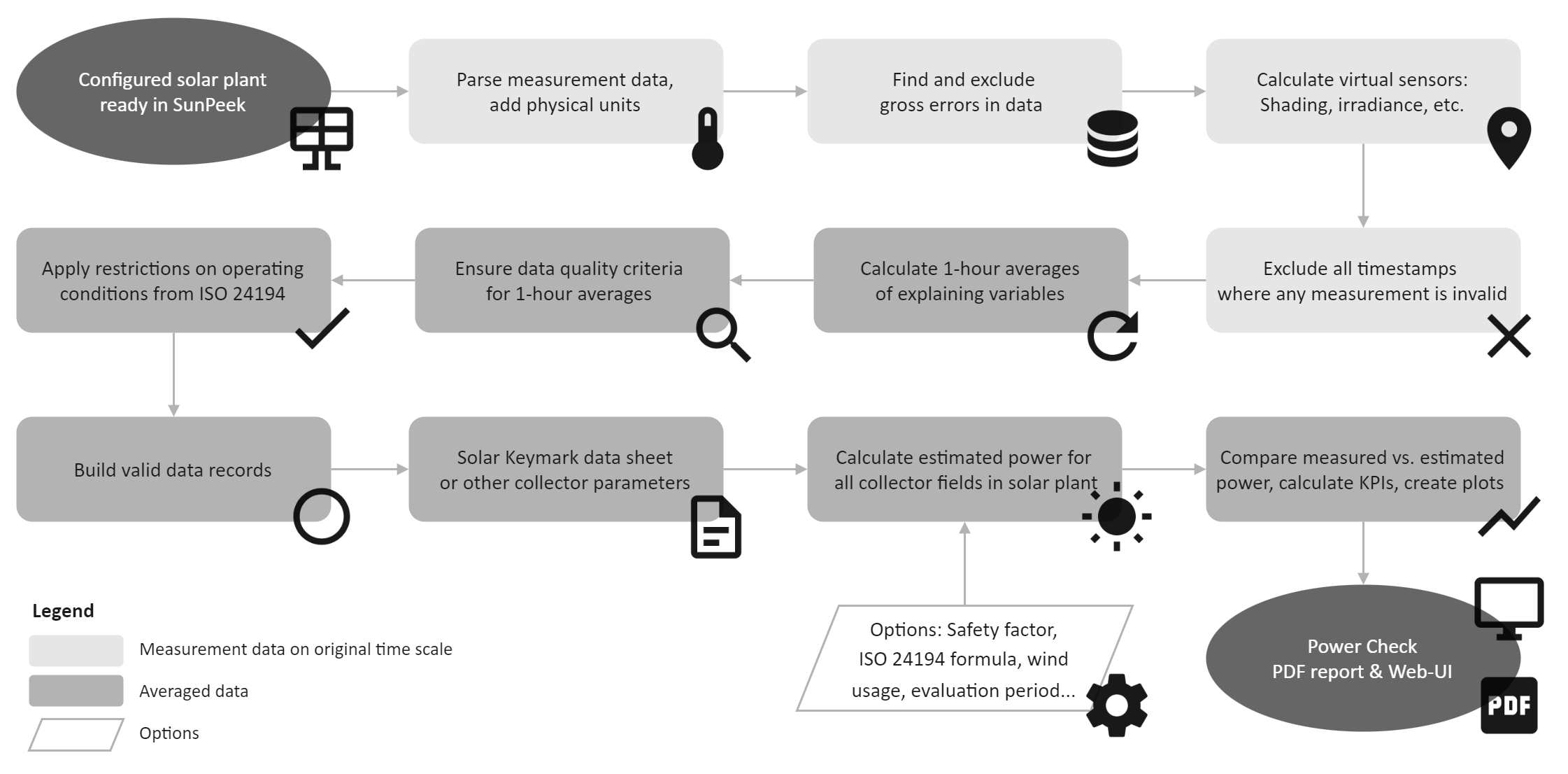
Overview of data processing steps for Power Check in SunPeek.#
Where can I find more information about Power Check?
For more information about Power Check, see the following resources:
The official ISO 24194 document, describing the procedure in detail.
The Guide to ISO 24194, which serves to supplement and clarify the ISO 24194 standard.
What are the different “formulas” used in Power Check?
ISO 24194 outlines three formulas or equations for calculating the estimated thermal power output of a solar thermal collector field.
Formula 1 is based on the collector’s optical efficiency and heat loss coefficient at normal incidence.
Formula 2 considers the incidence angle modifier for beam irradiance and is generally the preferred formula to use.
Formula 3 is for concentrating collectors with a high concentration ratio and does not consider the heat loss coefficient.
Note: This is based on ISO 24194:2022, and is subject to change in revisions of the ISO 24194 standard.
What are the measurement requirements for Power Check?
The figure below shows an overview of the required measurements for Power Check. Note that this is only one possible setup, and the exact sensor configuration depends on the collector technology used and on the plant hydraulics.
The required measurements for Power Check include:
Solar irradiance: Global, beam, and / or diffuse irradiance in the collector plane.
Ambient temperature: Measured near the collector field. Wind measurement is optional.
Collector temperatures: Inlet and outlet temperatures at the collector field or at the heat exchanger.
Thermal power output: Volume or mass flow rate of the heat transfer fluid.
The required or recommended accuracy levels for these measurements are defined in ISO 24194 and influence the overall uncertainty of Power Check results.
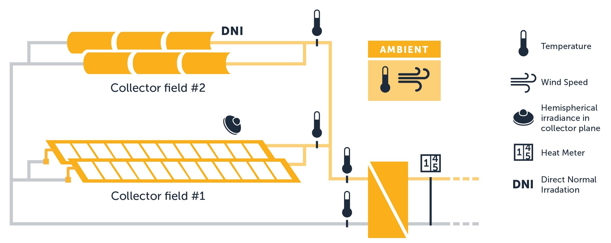
Overview of required sensor measurements for Power Check.#
What is the “safety factor” in Power Check?
The safety factor in Power Check is used to account for various uncertainties and unmodeled effects that can influence the difference between the estimated and measured power output of a collector field. Such effects can include piping losses, measurement uncertainties, and other factors.
What are “accuracy levels” in the context of Power Check?
Accuracy levels (I, II, and III) in Power Check are defined in ISO 24194. They define the allowable uncertainties for different measured quantities. Each accuracy level specifies maximum permissible errors or standard uncertainties for measurements like temperature, irradiance, and flow rate. For example, Level I typically represents the highest accuracy level with the strictest limits on measurement uncertainties. The standard requires stating the accuracy level when providing a performance estimate.
How are “stagnation events” handled in Power Check?
Stagnation occurs when the heat transfer fluid in the collector overheats because there’s no flow to remove the absorbed solar energy. The standard recommends excluding stagnation periods from Power Check analysis. However, specific criteria for defining and identifying stagnation events are not explicitly provided in ISO 24194. There are different approaches for handling stagnation, including the definition of stagnation based on temperature changes, the use of a minimum specific power output criterion, and potential challenges related to the interpretation of stagnation events.