

Radiation Conversion#
This page documents how SunPeek converts available radiation measurements into the tilted irradiance components used by collector arrays.
If a Power Check report shows Radiation: modeled instead of
Radiation: measured, the required radiation components were calculated by
one of these conversion models instead of being used directly from measured
real sensors.
The current implementation focuses on practically important cases where
collector-plane radiation can be derived from measured global, diffuse, beam,
or DNI inputs. In SunPeek, these measurements are mapped to the array input
slots in_global, in_beam, in_diffuse and in_dni. Depending on
the sensor orientation, they can be interpreted as measurements:
in the plane of the array, i.e. POA irradiance;
in the horizontal plane, i.e. horizontal irradiance;
in an incline plane different from POA.
Terminology#
SunPeek uses the following radiation quantities:
Symbol / slot |
Name |
Meaning |
|---|---|---|
|
measured global irradiance |
Hemispherical irradiance measured in the plane of the mapped sensor. |
|
measured diffuse irradiance |
Diffuse irradiance measured in the plane of the mapped sensor. |
|
measured beam irradiance |
Beam irradiance measured in the plane of the mapped sensor. |
|
measured direct normal irradiance |
Direct irradiance measure normal to the sun beam. |
|
global tilted irradiance |
Global irradiance in the plane of collector array (POA). |
|
beam tilted irradiance |
Direct/beam component in the POA. |
|
diffuse tilted irradiance |
Diffuse component in the POA. |
|
global horizontal irradiance |
Global irradiance on the horizontal plane. |
|
diffuse horizontal irradiance |
Diffuse irradiance on the horizontal plane. |
|
beam horizontal irradiance |
Beam irradiance on the horizontal plane. |
|
global tilted irradiance |
Global irradiance on a tilted plane (POA or other). |
|
diffuse tilted irradiance |
Diffuse irradiance on a tilted plane (POA or other). |
|
beam tilted irradiance |
Beam irradiance on a tilted plane (POA or other). |
|
direct normal irradiance |
Direct irradiance measure normal to the sun beam. |
|
angle of incidence |
Angle between the sun beam and the surface normal. |
The measured in_global value is not automatically the same as rd_gti.
They are identical only if the radiation sensor plane and the collector array
plane have the same tilt and azimuth.
Input slots and supported strategies#
Array radiation conversion uses four standard input slots:
in_global, in_beam, in_diffuse, in_dni
SunPeek describes available radiation inputs with a four-digit input pattern in
this exact slot order. Each digit is 1 if the corresponding sensor slot is
available and 0 if it is missing. For example:
1000 = in_global only
1010 = in_global + in_diffuse
1001 = in_global + in_dni
0110 = in_beam + in_diffuse
Same-plane POA cases without radiation modeling#
If the measured radiation components are already in the collector array plane, SunPeek can use them directly or calculate the missing POA component by simple closure. No decomposition or transposition model is required.
Implemented cases include:
0110 = BTI + DTI -> GTI by closure
0111 = BTI + DTI + DNI -> GTI by closure
1110 = GTI + BTI + DTI -> direct use of measured POA components
1111 = GTI + BTI + DTI + DNI -> direct use of measured POA components
1010 = GTI + DTI -> BTI by closure
1001 = GTI + DNI -> BTI by DNI geometry, DTI by closure
0011 = DTI + DNI -> BTI by DNI geometry, GTI by closure
For these cases, in_global, in_beam and in_diffuse must describe the
collector-plane quantities GTI, BTI and DTI.
Horizontal global irradiance cases#
If in_global has tilt = 0 deg, SunPeek interprets it as global
horizontal irradiance, i.e. GHI. The model first completes the horizontal
component set GHI, DNI, DHI and then transposes those components into the
collector array plane.
Implemented cases include:
1000 = GHI only -> decompose GHI into DNI and DHI
1010 = GHI + DHI -> calculate DNI from measured GHI and DHI
1001 = GHI + DNI -> calculate DHI from measured GHI and DNI
0011 = DHI + DNI -> calculate GHI from measured DHI and DNI
1100 = GHI + BHI -> calculate DHI and DNI from measured GHI and BHI
For 1010, in_diffuse must also be horizontal and is interpreted as
DHI. For 0011, in_diffuse must be horizontal and is interpreted as
DHI. For 1100, in_beam must be horizontal and is interpreted as
BHI. in_dni is direct normal irradiance and does not need orientation
metadata.
Global irradiance in an inclined sensor plane#
If in_global is not horizontal, SunPeek interprets it as global irradiance
in the measured sensor plane. The sensor plane may be identical to the
collector array plane or may have a different fixed tilt and azimuth.
Implemented modeled case:
1000 = measured global irradiance in sensor plane
0011 = measured diffuse irradiance in sensor plane + DNI
SunPeek reverse-transposes this measured global irradiance into horizontal
components and then forward-transposes those components into the collector
array plane. For 0011, SunPeek first calculates beam irradiance in the
diffuse sensor plane from DNI and closes global irradiance in that sensor
plane.
measured global irradiance in sensor plane
   -> GHI, DNI, DHI
   -> rd_gti, rd_bti, rd_dti in collector array plane
If the sensor plane and collector array plane are identical, SunPeek preserves
the measured global irradiance as rd_gti and calculates only the missing
POA components.
DNI-only input, i.e. input pattern 0001, is not sufficient to calculate the
full set of tilted components. DNI defines the direct normal beam component, but
it does not define the diffuse irradiance contribution. Therefore SunPeek does
not calculate rd_gti, rd_bti and rd_dti from in_dni alone.
Implemented transformations#
Both supported in_global-only strategies use the same intermediate
representation: horizontal irradiance components. The same representation is
also used for the supported auxiliary-input cases.
GHI, DNI, DHI
This means the radiation conversion can be understood as three separate transformations:
measured global irradiance in an arbitrary sensor plane -> horizontal components;
measured global horizontal irradiance -> horizontal components;
horizontal components -> collector-plane irradiance.
The implemented model chains are built from these transformations:
measured global irradiance in sensor plane
   -> POA-to-horizontal reverse transposition
   -> GHI, DNI, DHI
   -> horizontal-to-POA forward transposition
   -> rd_gti, rd_bti, rd_dti in collector array plane

measured GHI
   -> GHI decomposition
   -> GHI, DNI, DHI
   -> horizontal-to-POA forward transposition
   -> rd_gti, rd_bti, rd_dti in collector array plane
In code this is implemented in:
The core model functions live in
sunpeek.core_methods.virtuals.radiation:
get_horizontal_irradiance_from_gti(...)
get_horizontal_irradiance_from_ghi(...)
get_horizontal_irradiance_from_ghi_dhi(...)
get_horizontal_irradiance_from_ghi_dni(...)
get_horizontal_irradiance_from_dhi_dni(...)
get_horizontal_irradiance_from_dti_dni(...)
get_horizontal_irradiance_from_ghi_bhi(...)
get_poa_irradiance_from_horizontal_irradiance(...)
get_poa_irradiance_from_gti(...)
get_poa_irradiance_from_ghi(...)
get_beam_irradiance_from_dni(...)
The virtual sensor strategy
StrategyTiltedIrradiance_from_measured_inputs
classifies the available inputs by input pattern and sensor plane, then
orchestrates the required conversion. Cases that only need direct use, closure,
or DNI geometry are handled by the feedthrough strategy.
Transformation 1: POA global to horizontal components#
This transformation is used when in_global is not horizontal. The measured
value is interpreted as global irradiance in the sensor plane. The model
reverse-transposes this measurement into horizontal components:
measured global irradiance in sensor plane -> GHI, DNI, DHI
SunPeek uses pvlib.irradiance.gti_dirint() for this step.
Required inputs are:
measured global irradiance in the sensor plane
sensor tilt and azimuth
solar zenith and azimuth
timestamp index
ground albedo (default=0.25 (pvlib default value))
The AOI for the radiation sensor plane is calculated with
pvlib.irradiance.aoi().
The implementation uses the perez-driesse model option. The
delta_kt_prime stability index is used only when the time index is regular
and sufficiently short-spaced. For very short, irregular, or coarse time series,
SunPeek disables it so virtual sensor calculations can still run on small data
windows.
Transformation 2: horizontal global to horizontal components#
This transformation is used when in_global is horizontal. The measured
value is already GHI. Depending on the available auxiliary measurements,
SunPeek completes the horizontal component set in one of three ways.
GHI only#
If only in_global is available, the model decomposes this hemispherical
horizontal measurement into direct normal and diffuse horizontal components:
measured GHI -> GHI, DNI, DHI
SunPeek uses pvlib.irradiance.erbs_driesse() for this step by default.
The implementation also exposes the older pvlib.irradiance.erbs() model
as an alternative at helper-function level.
Required inputs are:
measured global horizontal irradiance
solar zenith
timestamp index
The decomposed components are returned as:
ghi = measured in_global
dni = decomposed direct normal irradiance
dhi = decomposed diffuse horizontal irradiance
GHI + DHI#
If in_diffuse is also available and horizontal, SunPeek interprets it as
DHI. The missing direct normal component is calculated from the measured
horizontal global and diffuse components:
measured GHI, measured DHI -> GHI, DNI, DHI
The implementation uses pvlib.irradiance.dni(), which is equivalent to
using the horizontal beam component BHI = GHI - DHI and projecting it onto
the sun-normal plane, with pvlib’s low-sun safeguards.
GHI + DNI / DHI + DNI / GHI + BHI#
If in_dni is also available, SunPeek uses the measured DNI and calculates
the missing diffuse horizontal component by closure:
BHI = DNI * cos(solar zenith angle)
DHI = GHI - BHI
This avoids empirical decomposition of GHI because the direct normal component is already measured.
If measured DHI + DNI is available, SunPeek calculates GHI by closure.
If measured GHI + BHI is available, SunPeek calculates DHI by closure
and derives DNI from the horizontal components.
These completed horizontal components are then passed to the same forward-transposition step used by the reverse-transposition chain.
Transformation 3: horizontal components to POA components#
This transformation is shared by both supported model chains. It transposes horizontal components into the collector array plane:
GHI, DNI, DHI -> POA global, POA direct, POA diffuse
SunPeek uses pvlib.irradiance.get_total_irradiance() with the
perez-driesse model for this step.
The returned plane-of-array components are mapped to SunPeek virtual sensors:
poa_global  -> rd_gti
poa_direct  -> rd_bti
poa_diffuse -> rd_dti
Special case: same-plane POA global measurement#
If the radiation sensor plane and the collector array plane have the same orientation in the reverse-transposition strategy, SunPeek preserves the measured global irradiance:
The beam component is still calculated from the modeled horizontal components. The diffuse component is then calculated by closure:
This keeps the modeled output consistent with the measured global irradiance in the collector plane. In this same-plane case, the following relationship is enforced:
If the sensor plane and collector plane differ, SunPeek uses the forward
transposed poa_global and poa_diffuse values.
The GHI decomposition strategy does not preserve in_global as rd_gti,
because in_global is a horizontal-plane measurement and rd_gti is a
collector-plane quantity. It always uses forward transposition to calculate
rd_gti.
Orientation metadata#
Both in_global-only strategies require orientation metadata for the measured
in_global sensor:
tiltazim
For fixed-mounted arrays, the collector array orientation is taken from the array
mounting configuration. For single-axis tracking arrays, SunPeek uses the
time-dependent collector orientation calculated as virtual sensors
surface_tilt and surface_azimuth.
The orientation decides which strategy is used:
horizontal sensor planes select horizontal-component completion and forward transposition;
collector-plane sensor inputs select feedthrough, closure, DNI geometry, or GTI reverse transposition as needed;
inclined sensor planes select reverse transposition from the sensor plane, followed by forward transposition to the collector plane.
For single-axis tracking arrays, non-horizontal radiation sensors are interpreted as collector-plane sensors moving with the tracker. Static sensor orientation metadata cannot currently describe a sensor plane that differs from the moving collector plane.
Validity limits#
POA-to-horizontal reverse transposition#
Reverse transposition from measured GTI uses
pvlib.irradiance.gti_dirint(). Its validity limits are based on AOI and
POA irradiance.
The pvlib documentation for pvlib.irradiance.gti_dirint() warns that
model performance is poor for approximately:
AOI > 80 deg
AND
POA irradiance > 200 W/m²
The AOI limit is consistent with Marion’s GTI-DIRINT validation discussion, where increased errors are reported for incidence angles in the 80–90 deg range. The exact 200 W/m² irradiance threshold is taken from the pvlib implementation documentation and should therefore be treated as a pvlib-recommended practical validity flag rather than a separately derived threshold from Marion (2015).
This is not a hard cutoff in pvlib. It is a documented region where GTI-DIRINT results should be treated with caution.
The implemented reverse-transposition path calls gti_dirint with
calculate_gt_90=False. According to the pvlib API, this means the model
returns NaN for AOI >= 90 deg. This is separate from the softer
poor-performance warning at AOI > 80 deg and
POA irradiance > 200 W/m².
SunPeek currently uses these limits in validation and diagnostic comparisons.
Validation comparisons keep only timestamps with AOI <= 80 deg or POA irradiance <= 200 W/m².
Equivalently, they exclude timestamps where both limits are exceeded at the
same time. The core model does not yet mask or remove calculated values inside
this documented poor-performance region.
A future implementation may expose a helper or virtual sensor such as:
rd_conversion_valid
or a function equivalent to:
valid = (aoi <= 80) | (poa_global <= 200)
Horizontal-global decomposition#
The GHI decomposition path uses pvlib.irradiance.erbs_driesse(). Its
validity limit is based on solar zenith.
erbs_driesse has max_zenith=87 by default. For timestamps where
solar_zenith > max_zenith, pvlib sets the decomposed DNI to 0:
solar_zenith > 87 deg -> DNI = 0
This cutoff is a built-in guard against unstable DNI values at very low sun positions.
Radiation model validation#
The implementation is validated with FHW and Condat operational demo data from the sunpeek_exampledata package.
Radiation validation#
The following figures show an example validation window from the FHW yearly
demo data utilizing the reverse-transposition conversion. The model uses only
measured rd_gti as input. The measured rd_bti and rd_dti sensors
are shown only as independent references.
Comparisons are filtered to timestamps with:
reference AOI <= 80 deg
OR
reference GTI <= 200 W/m²
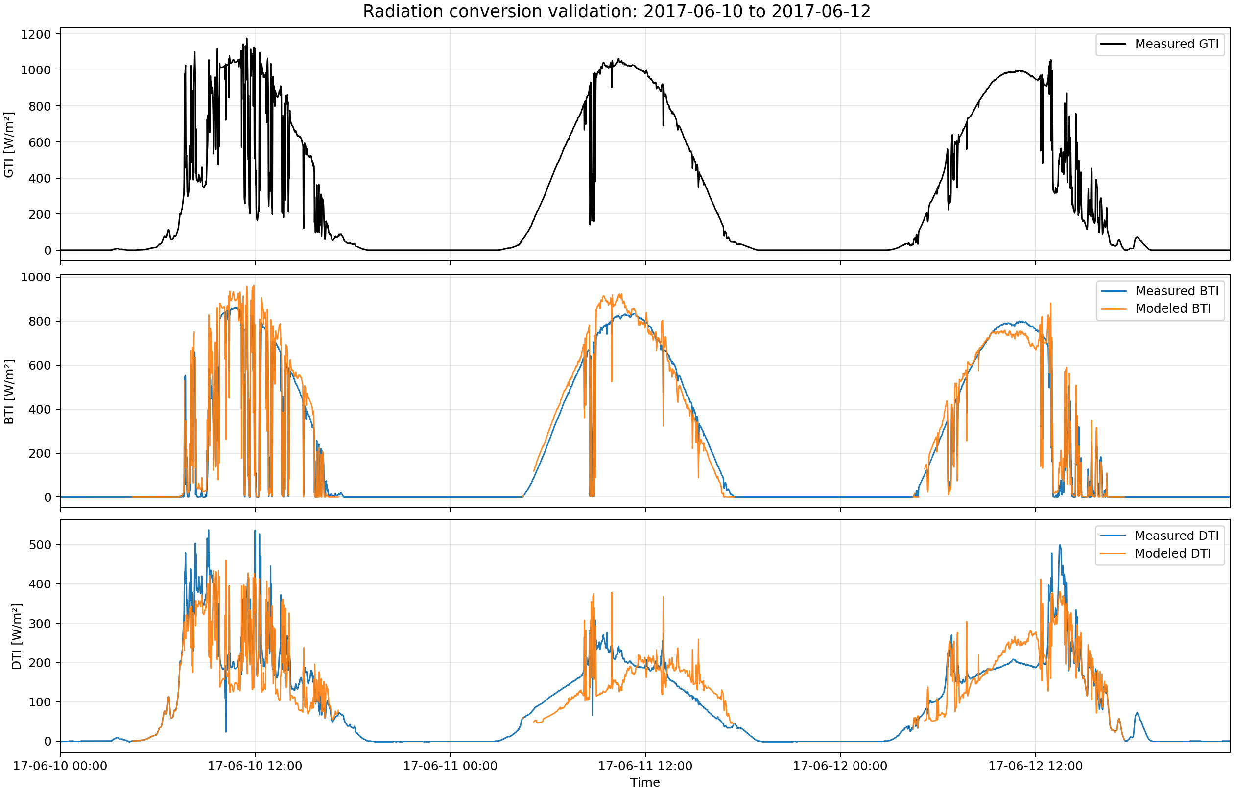
Modeled and measured tilted radiation components for a selected June time window. The plot compares modeled BTI and DTI against the corresponding measured FHW reference sensors.#
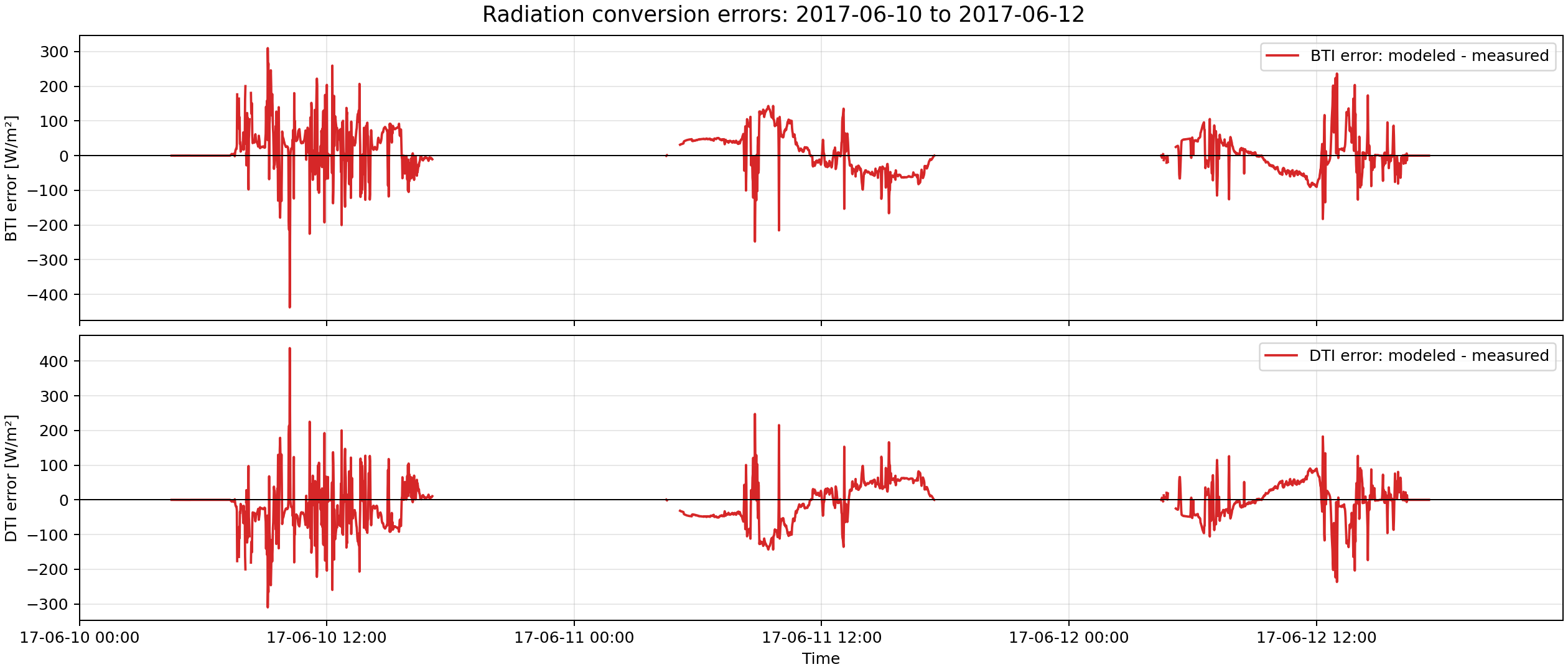
Error time series for the same June validation window, calculated as modeled minus measured irradiance.#
Power Check validation#
The radiation conversion also changes the automatic Power Check strategy
selection. Since BTI/DTI can be modeled from in_global, the Power Check can
be calculated using Formula 2 instead of Formula 1. This applies both when
in_global is measured in the collector/sensor plane and when in_global
is measured horizontally as GHI.
The numerical impact on Power Check is validated with the yearly FHW demo data for the measured-GTI conversion path. The test compares three Power Check runs:
Formula 2 with measured
rd_btiandrd_dti. This is used as the reference because it applies the same Power Check formula with independently measured radiation components.Formula 1 with measured
rd_gti. This represents the previous fallback when only global tilted irradiance is available.Formula 2 with modeled
rd_btiandrd_dtifrom measuredrd_gti. This represents the new radiation-conversion workflow.
The comparison is performed on common ISO Power Check intervals only, because Formula 1 and Formula 2 apply different irradiance restrictions and may therefore select different valid intervals.

Power Check output of (left) Formula 1 using measured GTI and (right) Formula 2 using modeled BTI/DTI, compared to the reference case using Formula 2 with measured BTI/DTI.#
All three approaches have similar performance for the FHW demo data, though Formula 2 using modeled BTI/DTI has a smaller mean absolute error and a smaller absolute bias than Formula 1. For other locations, Formula 2 using modeled BTI/DTI may have a larger advantage over Formula 1 because it uses a time-resolved beam/diffuse split instead of the fixed global-radiation approximation used by Formula 1.
Power Check validation for single-axis tracking arrays#
For single-axis tracking arrays, the GTI-only conversion path was checked with the yearly Condat solar plant demo data. Since no independent measured BTI/DTI reference is available for this case, the comparison is not a radiation model validation. Instead, it compares the resulting Power Check estimates from:
Formula 1 using measured tracker-plane GTI;
Formula 2 using BTI/DTI modeled from the same measured GTI.
Only common Power Check intervals are compared. The two estimates are very similar for the demo data, indicating that the radiation conversion produces radiation values of acceptable quality for the Power Check for this tracked example.
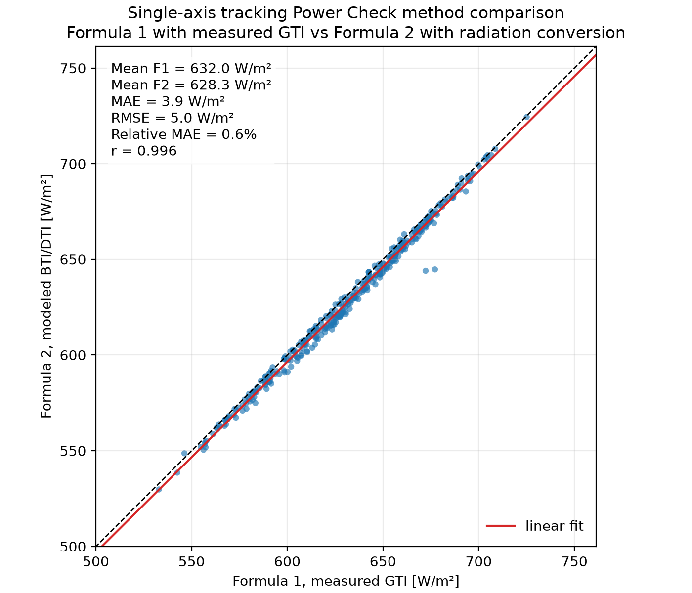
Power Check estimates for the single-axis tracking demo data. Formula 1 uses measured tracker-plane GTI. Formula 2 uses BTI/DTI modeled from the same measured GTI utilizing reverse-transposition.#
Limitations#
The current implementation has the following limitations:
tracking arrays, non-horizontal radiation sensors are interpreted as collector-plane sensors moving with the tracker
tracking sensors in a plane different from the moving collector plane are not supported
DNI-only input is not sufficient for full tilted irradiance conversion
model quality depends on sensor orientation metadata
high-AOI conditions can produce poor reverse-transposition results
GHI decomposition accuracy depends on the decomposition model and will be validated separately when suitable measured reference data are available
pvlib may emit convergence warnings for some timestamps
AOI and irradiance validity limits are currently used in validation, but not applied as hard output masks
References#
The implementation is based on pvlib’s irradiance modeling functions:
Relevant literature:
Erbs, D. G., Klein, S. A., and Duffie, J. A. (1982). Estimation of the diffuse radiation fraction for hourly, daily and monthly-average global radiation. Solar Energy 28(4), 293-302. DOI: 10.1016/0038-092X(82)90302-4.
Marion, B. (2015). A model for deriving the direct normal and diffuse horizontal irradiance from the global tilted irradiance. Solar Energy 122, 1037-1046. DOI: 10.1016/j.solener.2015.10.024.
Driesse, A., Jensen, A. R., and Perez, R. (2024). A continuous form of the Perez diffuse sky model for forward and reverse transposition. Solar Energy 267. DOI: 10.1016/j.solener.2023.112093.